

Pantograph Disconnectors
Type GSSB up to 550 kV

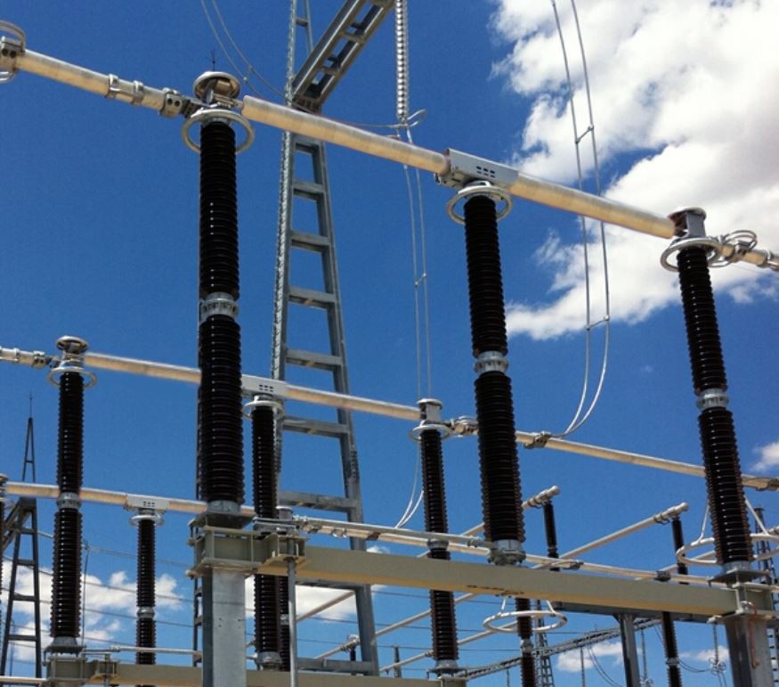
The pantograph disconnectors consist of three poles. Each pole consists of one support insulator, one rotating insulator, the pantograph mechanism and a counter contact.
• More than 75 years of experience
• Durable and reliable design
• Over 120,000 disconnectors and earthing switches are in service in more than 100 countries throughout the world
• Virtually maintenance-free
• More than 75 years of experience
• Durable and reliable design
• Over 120,000 disconnectors and earthing switches are in service in more than 100 countries throughout the world
• Virtually maintenance-free
Insulators
The disconnectors can be equipped with insulators in accordance with IEC, ANSI, or DIN specifications.
Pantograph mechanism
The pantograph mechanism is installed on the support insulator and transfers the movement of the rotating insulator to the arms of the pantograph disconnector. The mechanism is housed in an aluminum enclosure, protecting it against pollution and ice. The springs that compensate for the weight of the pantograph arms are also installed in this housing. Each pantograph is equipped with four aluminum arms to ensure a rigid construction with a very high short circuit rating.
The main contacts are made of copper, with a silver-plated surface. The counter contact is a horizontal copper bar, silver-plated, which has to be connected to the busbar system.
The main contacts are made of copper, with a silver-plated surface. The counter contact is a horizontal copper bar, silver-plated, which has to be connected to the busbar system.
Earthing Switch
Hapam pantograph disconnectors may be equipped with earthing switches. The earthing switch consists of an aluminum tube, provided with silver-plated contacts at both ends.
Drive mechanism
The disconnectors and/or earthing switches can be single-pole or three-pole operated by means of a motor-operated drive mechanism or a manual-operated drive mechanism.
In case only one drive mechanism is used for three-pole operation, the poles are interconnected by means of adjustable coupling rods. The drive mechanism also houses the auxiliary contacts for position indication.
In case only one drive mechanism is used for three-pole operation, the poles are interconnected by means of adjustable coupling rods. The drive mechanism also houses the auxiliary contacts for position indication.
Testing
The disconnectors and earthing switches are designed and tested in accordance with the latest IEC specifications. Hapam maintains a quality assurance system according to ISO 9001, certified by DNV GL (previously known as KEMA).
Installation
The disconnectors and earthing switches are pre-assembled and adjusted in our works as completely as possible. The construction is designed so that all disconnectors can be installed and adjusted at the site very easily, without the need of any special tools. Hapam provides clear installation instructions and assembly drawings.
Maintenance
The disconnectors and earthing switches supplied by Hapam are designed to ensure that they are virtually maintenance-free. However, to warrant a long and trouble-free service period, we advise that a visual inspection of the contacts and bearing points be carried out at regular intervals.
| Rated Voltage | kV | 123 | 145 | 245 | 550 | |
|---|---|---|---|---|---|---|
| Lightning Impulse Withstand Voltage | ||||||
| to earth | kV | 550 | 650 | 1050 | 1550 | |
| across the isolating distance | kV | 630 | 750 | 1200 | 1550 | |
| + 315 | ||||||
| Power Frequency Withstand Voltage | ||||||
| to earth | kV | 230 | 275 | 460 | 620 | |
| across the isolating distance | kV | 265 | 315 | 530 | 800 | |
| Lightning Impulse Withstand Voltage | ||||||
| to earth | kV | – | – | – | 1175 | |
| across the isolating distance | kV | – | – | – | 900 | |
| + 450 | ||||||
| Current and Short Circuit Ratings | ||||||
| 3150 A-125 kA peak – 50 kA/3 sec | ||||||
| 4000 A-160 kA peak-63 kA/3 sec | ||||||
Related Products
Double-break Disconnectors
Type SSBIII up to 550 kV

Centre-Break Disconnectors
Type SSBII up to 550 kV

Vertical Break Disconnectors
Type VSSBIII
Need Assistance?
Get in touch with
us!
Our dedicated sales engineers are here to help you with your inquiries about our products
and services.